A few weeks ago I upgraded the Az / El satellite antennas in the backyard to a new UHF yagi. The previous Diamond A440-S15 antenna was working fine, but I wanted to try the M2 440-18 (18-element) yagi for slightly higher gain on UHF. The installation went well, but unfortunately the slightly longer antenna impacted the house roof as the array was rotating around to line up with a satellite pass. Oops!!

Turns out the drive motor in the Yaesu G5500 azimuth rotator had burnt out. Symptoms on disassembly were a burnt smell (obvious), along with a mismatch in coil resistance indicating that one of the coils had shorted from overheating. The coils are series-wound, and should be roughly 7 ohms total, or 3.5 ohms each (red to black, green to black should both be 3.5 ohms; red to green should be 7 ohms). My motor had one winding with only 1.0 ohm resistance, clearly shorted. I'm not sure how long the motor was stalled for, but probably for quite some time in order for the motor to heat to this point. Interestingly, the G5500 controller fuse did not blow - I found out later that the 24V AC motors used in this rotator draw pretty much the same current at free run, under load, and at stall. Therefore, even though I had previously installed the smallest fuse that would work under normal operation without blowing (1A as opposed to the factory-installed 2A fuse), the fuse never needed to blow to protect the controller. Instead, the motor simply overheated and shorted:

A quote for motor repair (rewinding) from a company in LA came to $365 -- about 3X what the motor costs new. Replacement motors are currently unavailable at Yaesu Parts (March 2012) due to supply issues from Yaesu Japan. In order to move things ahead, I decided to go ahead an purchase a complete G5500 system to use as a spare, and I could directly swap the azimuth rotator into the antenna array in the backyard.
Before I installed the new rotator, I disassembled it to install a thermal switch (cutoff point 75C). The thermal switch is wired in series with the black (common) lead to the motor, and is directly attached to the motor housing. This way, if the motor starts to go over-temperature, the thermal switch will cut power to the motor and prevent any overheat problems. Bench-testing indicates that the switch will shut off the motor after roughly 10-15 minutes continuous operation at 65F ambient temperature. I'll have to wait until summer (with air temps of 100F+ and solar heating of the rotator chassis) to see if there is enough margin in the thermal switch to keep it from cutting off too soon with normal operation ... I suspect a 100C switch might be a bit more useful.
Here's the process for installing the thermal switch:

The thermal switch is uninsulated, use heat-shrink tubing to insulate leads and body.

This process works for the Yaesu G5500:

Place a matchmark on the chassis for future reference:

IMPORTANT: do the following steps inside a box -- if you mess up, the ball bearings will go running 100 different directions at once!!
Flip the rotator upside down and remove the four bolts holding the lower bearing ring:

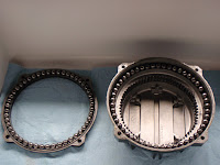
Grab the rotator, holding the lower bearing ring, and flip it upright. Carefully (!) lower the lower bearing ring and ball bearings down from the rotator. The ball bearings sit in a nice groove on the ring, as long as you keep the ring level the bearings will stay in place:

Now lift the rotator off of the lower bearing ring, taking care to grab the entire unit at once. Carefully invert the rotator and lay it upside down again:

Lift the rotator bottom straight up off of the rotator upper. The remaining bearings will stay inside the race inside the rotator upper. Be extremely careful to lift the rotator bottom level and sraight up, so you can note the position of the limit switch lever.

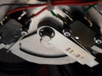
While continuing to lift the rotator straight up, carefully examine the position of the limit switch lever from underneath. Take note (!) of the orientation of the limit switch (towards the right lever or left):

Turn the rotator upside down again and set it down:

The internal motor and gear assembly can be pulled after removing the three bolts holding it on. Solder the thermal switch into the common (black) lead, and zip-tie the switch to the motor:

A close-up of the thermal switch. Note that heat-shrink tubing was used to insulate the body and leads:

Reassemble the rotator in reverse order, paying special attention to the position of the limit switch lever, and the match-marks on the rotator housing. Once reassembled, bench-test the rotator for normal operation:

Aligning the rotator halves from scratch, if the original positioning is lost for example, is not that difficult. The linear position sensor potentiometer has a 500-ohm range, of which 450 ohms is used during the 450 degrees of rotator travel. Therefore, the sensor changes by one ohm per degree of travel. Connect an ohmmeter to the sensor common and one of the sensor outputs and measure the resistance. While monitoring the resistance, run the motor for counterclockwise rotation of the rotator head. Check that the resistance goes down -- if it's going up as you rotate counterclockwise, you're monitoring the wrong sensor output and select the other one. Verify that your position monitoring is working: you should be able to run the assembly close to 0 degrees (ohms) counterclockwise, and close to 500 degrees (ohms) clockwise. Next, drive the gear assembly to the position where the resistance reads 65 ohms. (Setting the position at 65 ohms, and installing the rotator upper half in the 45 degree position, will give you 20 degrees clearance on the sensor below zero degrees rotation, and about 30 degrees of clearance past 450 degrees rotation.) Position the limit switch lever towards the right (looking at the rotator with the multi-pin connector facing you). To install the upper rotator half at 45 degrees, look at the upper rotator shell and locate the vertical matchmark on the outside rim. This matchmark will line up with a similar matchmark just above the 8-pin connector. Set the upper shell down on the lower housing such that the matchmarks line up as close as possible. At this point it helps to mark the protruding rectangular tabs on the upper housing with degree values: the one to the left of the matchmark is 0 degrees, the one to the right is 90 degrees, and so on. The rotator is now positioned at 45 degrees and the resistance from the sensor should read 65 ohms. Rotate the rotator counterclockwise and verify that the rotator comes to a stop at zero degrees; the resistance here will be around 20 ohms. At zero degrees, the tab you marked with "0" will be directly above the multi-pin connector. Next rotate the rotator clockwise and verify that it comes to a stop at 450 degrees; the resistance here will be around 470 ohms. The tab marked "90" will be directly above the multi-pin connector. Rotate the system back to a reading of 65 ohms and verify that the matchmarks line up. Alignment is complete.
And three weeks later, back on the satellites!

Very cool Dave! This will be a great resource for many people. Nice work on the photography of the process too.
ReplyDeleteCatch you on the birds.
73's
KN6ZA
Thanks Andy!! 73 de Dave
ReplyDeleteThanks, you are one of the very few people to show the unit and describe the motor.
ReplyDeletemy need is to drive a heliostat and for that, I would want a DC motor. it looks like I could replace the AC motor with a DC motor, if I could make the proper mounting brackets to fit in the unit.
thanks again.
Dave in NJ
Dave in NJ
sorry I could not log in with my e-mail.
Thanks Dave for your information regarding the G-5500 repair. I have had the same problem like you a while ago and solved it using your posts. Now its up and running again.
ReplyDeleteYou stated "I found out later that the 24V AC motors used in this rotator draw pretty much the same current at free run, under load, and at stall."
Can you can tell me what is the measured current consumption ?
Do you have a diagram/ description (pin 1-6) for the Az/EL terminals on the real panel of G5500 controller? What are the 6 wires used for?
Any information would be appreciated.
Thanks in advance,
Paul