DISASSEMBLY
There is a schematic for the ATAS-120 available online if you search for it. If you're going to do any work on the antenna, it's a very good idea to take a look at how the unit is constructed in the diagram below:

First, fully extend the antenna, then remove the ATAS-120A from the vehicle mount:

Personally, I like to use a little bit of coax seal to add weatherproofing to the cap. This is removed next:

Remove the coax seal:

Grab the rubber weatherstripping boot on top:

And slide off the boot, exposing the hex screws that anchor the whip:

Loosen the hex screws:

Remove the whip and the boot and set it aside:

Now take the hex screws all the way out:

And carefully set them aside as well:

Once the hex screws securing the top of the weather shield are removed, the outer weather shield (which Yaesu calls the Cover Assembly) can slide right off. Push upwards from below:

Now you can set the outer cover assembly aside:

Next step is to remove the base containing the matching assembly. Pull up on the rubber ring:

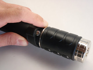
There are three silver screws underneath the ring:

Remove the silver screws:

Note: I've actually replaced one of the nylon washers with a stainless steel lock washer, and have buffed off the paint where the screw/washer connect to the black tube. The reason for this is to maintain a good RF contact between the matching assembly and the top tube, overcoming any potential open circuits caused by an inner O-ring, the nylon washers, and the paint and possible corrosion. The screw / lock washer assembly can be sealed with a small amount of coax-seal around the perimeter of the screw.
And put a matchmark between the tube and the matching assembly for later assembly:

Now the tube is unscrewed from the base, carefully work the matching assembly off of the tube. There's no way to stress this enough. Carefully. CAREFULLY. Once that O-ring on the base is clear of the tube, there is NO friction holding the two together and it's super easy to yank the motor wires right out. Slowly and carefully:

Carefully slide the matching assembly out of the tube:

Further:

You can now see the motor connector, it unplugs easily:

Unplug the motor connector and separate the top from the matching assembly:

Set the matching assembly aside:

One thing I have noticed is that over time, the connection between the matching assembly and the outer tube can become intermittent. Symptoms of this are "fluttering" on receive, reports of clipping in transmitted audio, and intermittent continuity when checking tip-base circuit with an ohmmeter while "wiggling" the tube against the match. Partly because of corrosion, partly because of the rubber O-ring, and partly because of the nylon washers on the three screws that secure the tube, it really isn't the best connection. What I have done is to clean the top of the matching assembly thoroughly, then clean the inside of the tube. Adding compound like anti-sieze (to prevent the tube from corroding to the matching assembly, as some have reported) only seems to make the intermittent connection worse, so instead of this I've just been keeping the whole connection clean. Also, the use of a steel lock-washer instead of a nylon washer (above) helps to maintain a good RF connection between the match and the rest of the antenna.
And now make a matchmark where the top assembly (which Yaesu calls the Terminal Holder) inserts into the tube:

There are three black screws in the middle of the tube. Remove them:

And set the three black screws aside:

Next, remove the three silver screws securing the terminal holder to the top of the tube:

Note that one of the screws is secured under a silver label:

Slide the terminal holder assembly out of the tube:

Further:

And separated:

Now you can see the entire coil, motor, and terminal holder assembly:

The black tube is just a hollow aluminum tube:

Here's a view of the motor assembly:

And a view of the coil and terminal holder assembly:

Here's a close-up of the terminal holder assembly. The silver springs secure two ball bearings each. The ball bearings connect the slider (fixed in the outer black tube) with the wire coil (which slides in and out).
After 6 months of mobile operation, I was starting to get a little "fluttering" on the antenna as it moved. It turns out the spring clips over each ball bearing weren't pushing down quite hard enough, allowing the coil to move against the balls. Simply unscrewing the small philips-head screw securing each spring clip, and slightly bending the clips inwards towards the ball bearings, and reinstalling, solved the problem. You can see the clips clearly in the photo below:

My coil had fine "grooves" in the wire where the bearings ran over them (after 3 months of use), along with a fine copper dust inside. Reportely, this is normal.

ASSEMBLY
Assembly is simply the reverse of disassembly. Be sure to avoid catching the motor leads when reinserting the base into the tube.
While I had each unit apart, I wiped it down with a dry cloth (to remove the copper dust), and checked for water intrusion or other problems. I also checked to make sure all of the gaskets and O-rings looked good.
REPAIR OF THE MATCHING SECTION
Disassembly and reassembly of the matching unit of the ATAS-120A is a fairly involved procedure. The unit is a sealed assembly and needs no regular repair or maintenance. Inside the matching assembly is a copper coil that connects the lower chrome portion of the assembly with the upper portion, with a few capacitors soldered from sections of the coil to the center conductor. The coil is wrapped around a plastic form, and the center conductor is hidden within this form. The outer (black) plastic shell is about 1/8" thick.
There are a few reports online that the internal coil solder connections can become cracked, so it may be of interest to open the unit up for inspection from time to time. However, use caution when doing this! It is possible that the majority of the situations of poor antenna connections are either in the antenna mount itself, or more likely in the SO-239 center conductor that mates with the PL-259 pin on the antenna. If this center conductor on the mount is bad, there is no point in disassembling the matching unit! It's also possible that the online reports of coil failure are based on early versions of the coil.
The procedure for disassembly of the matching unit from an ATAS-120A is as follows:
Disassembly
0. All work can be done with the top section connected to the matching unit.
1. Locate the upper and lower pins (silver) on the matching unit.
2. Using a sharp knife, cut away the plastic around the lower pin. Try to remove plastic in at most a 1/4" diameter hole around the pin. You'll have to dig down fairly deep until you hit the shiny chrome steel ring that the pin secures into.
3. Try pulling the pin straight out using needle-nose pliers. One internet report indicates this pin can be pulled out using locking needle-nose pliers, but this may be doubtful. The pin is secured into roughly 3/8" of brass below this point, it's not going to come out easy.
4. Snap the pin off at the base. This is fairly easy to do by putting the matching unit in a padded vise, and then tapping the pin in different directions with a center punch. After a few taps in each direction, the pin will snap right off. The pin is stainless steel and is very hard/brittle.
5. Use a moto-tool and a narrow (1/16") diamond bit to grind the existing 1/4" hole down into the brass, following the stainless steel pin. Using a moto-tool you can physically feel the pin (hard stainless steel) embedded in the softer outer brass, and use the pin itself as a guide. Keep the hole as narrow as possible. Stop "drilling" when you reach a depth equal to the inner diameter of the inner threaded portion of the lower brass mount (roughly 3/8"). As an alternative to grinding, you can use a drill press, but it may be very difficult to keep the drill bit centered on the stainless pin amidst the brass.
6. When you're finished, you will have a 1/4" hole drilled straight down into the inner threaded brass ring. The outer chromed brass mount will then unscrew easily from the outer black plastic housing. There is a rubber O-ring (1-1/8" diameter by 1/16" thick) that may be destroyed when you unscrew the housing. If the outer chromed brass mount does not unscrew smoothly and evenly, or if the internal PL-259 connector rotates as the outer mount is turned, you have not drilled deep enough and the outer/inner threaded sections are still connected. Do not turn any more, or you will rip the internal solder connections from the internal coil. The center PL-259 plug is NOT intended to move with respect to the upper housing, if you see it move, stop. Drill slightly deeper and try again.
7. Unscrew the lower threaded chromed brass mount.
8. Put a small notch between the upper pin and the upper chromed brass mount. The notch doesn't have to be very big, only 1/16" x 1/16" and 1/8" deep.
9. You can now pull the outer plastic housing away from the upper chromed brass mount. There is another O-ring inside; since the housing pulls straight off, the O-ring should be undamaged.
10. The internal coil is now visible for inspection and repair if necessary.
11. The lower portion of the PL-259 and the upper housing are connected with the copper coil and should have zero ohms resistance. The center pin of the PL-259 is connected to the center of the PC board and should also have zero ohms resistance (the top tube of the antenna must be removed to access the PC board).
Reassembly
1. In the lower chromed brass mount, drill out the hole (that originally contained the steel pin) with a #21 drill bit. Be sure the hole is straight and clean.
2. Use a #10-32 tap to put threads into the hole.
3. Put the outer plastic housing back on the upper chromed brass mount.
4. Thread the lower chromed brass mount back into the upper housing.
5. Insert a 3/4" (or longer) #10-32 allen-head screw into the lower chromed brass mount.
6. When the screw bottoms out, give an additional 1/4 turn.
7. Remove the screw. Remove the lower chromed brass mount.
8. Identify the gouge in the inner PL-259 threads from the allen screw. Carefully drill out this area roughly 1/32 inch deep, just enough to provide an area for the allen screw to seat and lock the two threaded components together.
9. Reassemble the unit and verify the allen screw seats properly and locks the two threaded units.
10. Rebuild the lower half of the outer plastic housing. I used a small metal washer, cut in a D-fashion to fit the lower lip of the housing. The cut washer can be positioned with the allen screw in place, marked, and then the housing disassembled and removed. Masking tape was then used to form a dam on the inside of the housing, and the entire area was filled with epoxy. After the epoxy set, the entire area was shaped and re-drilled for the allen screw.
11. Insert the O-rings (use new ones if necessary).
12. Reassemble the unit. Tighten the allen screw. Apply a small amount of coax-seal to weatherproof the allen screw.


