
I've been upgrading my station to improve EME (earth-moon-earth) capabilities. Many components of the station are already set for EME -- since I work the satellites primarily, I already have the azimuth-elevation rotator (a Yaesu G5500), yagi antennas (18 elements on 70cm and 7 elements on 2m), computer control, and computer sound-card interfacing with the radios. This has allowed me to run the WSJT software in JT65B mode and copy some of the stronger signals reflected from the moon, and make a partial contact with K5GW in Texas last year. The goal this year is to produce a higher uplink power, as well as have improved gain and sensitivity in the antennas. A key aspect was to not have the EME upgrade interfere with the existing satellite capability.

For now, I'm focusing on the 2-meter band (144.105 to 144.150 MHz). It's challenging because of high local noise in that band, but there are more EME stations on 2m than the other bands combined. Here's a rundown of the station upgrades:
12V DC Power
I've upgraded to an Astron RS-70M power supply, that can put out up to 70 amps at 13.8 volts DC. I've also been working on a surplus computer server power supply (JD-200) that can produce 110 amps, but the supply generates a fair amount of RFI so that will be a longer-term project.

300 Watt Output
I'm borrowing a 300-watt amplifier from WB6EBR. By feeding a 5-watt signal from the FT-817ND radio into a RF-Concepts 2-23 amplifier, the signal is boosted to around 35 watts. The 35 watts directly feeds a Mirage 5030 amplifier, which will output close to 300 watts at this drive level.

Cooling Fans
The amplifiers and the radio can generate quite a bit of heat during the long (50-second) transmit periods and high duty cycle (50%) that the JT65B mode uses. A 6-inch cooling fan sits above the Mirage amplifier to keep it cool, and a 4" cooling fan sits behind the FT-817ND radio to cool it. Temperatures without the fan reach > 120F after 10 minutes, with the fans temps are kept to around 85F or so.
Frequency Stability
As the long transmit cycles generate more heat in the radio, the default crystal oscillator drifts slightly in frequency as the system warms up. The drift is around 5 to 10 Hz per minute, which is enough to interfere with proper decoding of the very-tight tolerance JT65B signals. I replaced the stock oscillator in the FT-817ND with a Yaesu TXCO-9 temperature-compensated crystal oscillator, that has much better improved frequency stability. This reduces drift, and will help in decoding very weak signals.

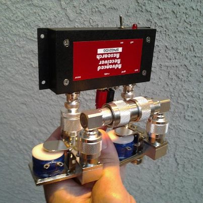
Preamplifier Bypass
The VHF preamplifier at the antenna is rated to tolerate 25 watts of RF transmit power, and would quickly be destroyed by the 300-watt amplifier during transmit. To protect the preamplifier, two Tohtsu CX-520D coaxial relays surround the preamplifier in a bypass configuration. By default, with now power, the relays allow the antenna to be connected directly to the amplifier, with the input/output of the preamplifier grounded. When energized,the relays switch input/output connections to allow the antenna to be connected to the preamp, and the preamp to the radio. The bypass relays are de-energized during transmit cycles to protect the preamp.
Sequencer
When high-power transmittion is initiated from the computer control, a series of events needs to happen in a specific order. First, the preamplifier must be shut down. Next, the bypass relays around the preamplifier must switch to connect the antenna directly to the high-power amplifier and bypass the preamp. After that, the high-power amplifier can be turned on. Lastly, the radio can be allowed to produce transmit power. I built a sequencer to control these events with a specific order and timing -- first prototyped on a breadboard using a core schematic from the internet, then assembled with discrete components onto a perfboard. On the transmit signal from the computer, the FT-817ND grounds a TX pin at the rear of the radio. This is detected by the sequencer, which then charges a 10 uF capacitor. As the capacitor charges, the voltage is compared to a reference voltage divider network at four voltages (channels), and as each threshold is crossed a trigger is sent to close a relay. Relay #1 removes power from the preamplifier on the mast. Relay #2 removes power from the bypass relays putting them in safe mode. Relay #3 sends a ground signal to enable the high-power amplifier. Relay #4 releases the TX Inhibit signal on the FT-817ND radio allowing it to transmit. The four relays close in order, with a delay of around 150 milliseconds each.


Stacked Antennas
To improve transmit gain as well as receive sensitivity, I added a second M-squared 2M7 yagi antenna. Previously I had the 70cm antenna on one side of the rotator cross-boom, and the 2m antenna on the other. In the new configuration, the two 2M7 antennas are vertically mounted on either end of the crossboom (separated by 6 feet 8 inches), and the UHF yagi is mounted horizontally above the rotator. Power is transmitted to both 2m antennas via a M-squared power divider and phasing harness.
Initial Results
The day after assembling the power supply, amplifier, relays, and sequencer system (it took about 3 weeks to get this all together), I was able to make quick contact with HB9Q in Switzerland via moonbounce. During that QSO two other stations (in Great Britain and Mexico) reported seeing my signals also. This was my first confirmed EME contact, woohoo! At this time I haven't tested the additional 2m antenna.
The photos below show the WSJT software screenshots from the QSO, as well as the antenna of the other station -- lots of gain there!


Here is my first EME QSL card -- pretty exciting to get the paper confirmation of a 2-way contact via signals reflected from the moon!!


Very informative...
ReplyDeleteI did not try EME till now because I was afraid the vertical polarization will not work...
73 and gd luck!
Corneliu YO4AUL
Great info. Where did you get the coax relays?
ReplyDeleteI have a GT-550 on order and will be installing it with my 12 element M2 antenna.
73, Ted, WF0N
Thanks for posting!
ReplyDeleteAny updates to share?
K4YR