Thursday, March 29, 2012

Yaesu G5500 Rotator Motor Repair

As described in an earlier post, a few weeks ago I burnt out the azimuth portion of my Yaesu G-5500 rotator (similar to a G-5400) after the antenna array accidentally hit the rooftop. Yaesu USA parts currently (March 2012) has no replacement motors in stock (typically around $130), and a professional motor rewinding company quoted $360 to rewind the motor.

I decided to rewind the motor myself. The whole process was actually very straighforward, if somewhat tedious and time-consuming (about 10 hours work), but it was a lot of fun taking the motor apart then rebuilding it. The following photos show the steps in the process.

Here's the disassembled motor, with the end-caps and rotor removed:


The rear of the motor board, with the circuit board attached. The wires normally go though an insulated hole in the end-caps:


The front of the motor, note how the red/green/black wires wrap around the coils:


The circuit board:


With the circuit board removed, it's easy to directly measure the individual coil resistance:


0.4 ohms -- yep, it's certainly shorted!!


In order to get the coils out, the individual motor laminations need to be removed one-by-one. It's a tedious process, and took about 2 hours. There are 58 laminations. I marked diagonal lines on the outside of the stack to aid in reassembly, and also numbered each lamination as it was removed. They're on there pretty tight, and each one needs to be pried off:


Close to having all the laminations removed -- you can see the individual coils clearly now:


Yay! All 58 laminations removed and stacked separately:


The coils are protected by black tape which is easily removed:


And the four coils easily pull off the star-shaped inner lamination stack.


Each coil is about 2" x 1", and contains 158 turns of a single wire 620" long:


The wire from each coil weighs 22.0 grams. This equates to 0.932 lb / 1000', or about 25-gauge. I also measured the resistance of the wire (about 1.8 ohms), which also equates to around 25-gauge. Finally I measured the wire with a micrometer, and the diameter (about 0.0179") confirmed it's 25-gauge wire.


Here's my master drawing of the circuit board and wiring connections. It was very important for being able to connect the coils and power cables back correctly:


My winding jig was ugly but practical -- it consisted of a variable-speed drill controlled by a home-made foot pedal:


The drill chuck held a wooden form that neatly fit inside the center of the square coil windings. One one side of the form is a spring clamp that holds a magnet:


The empty coil housing shown here slips over the top of the wooden form. Two of the four coils were shorted, and the overheating had fused the insulation in the windings. The wire still pulled off of the housing fairly easily, and the housing itself was not damaged at all:


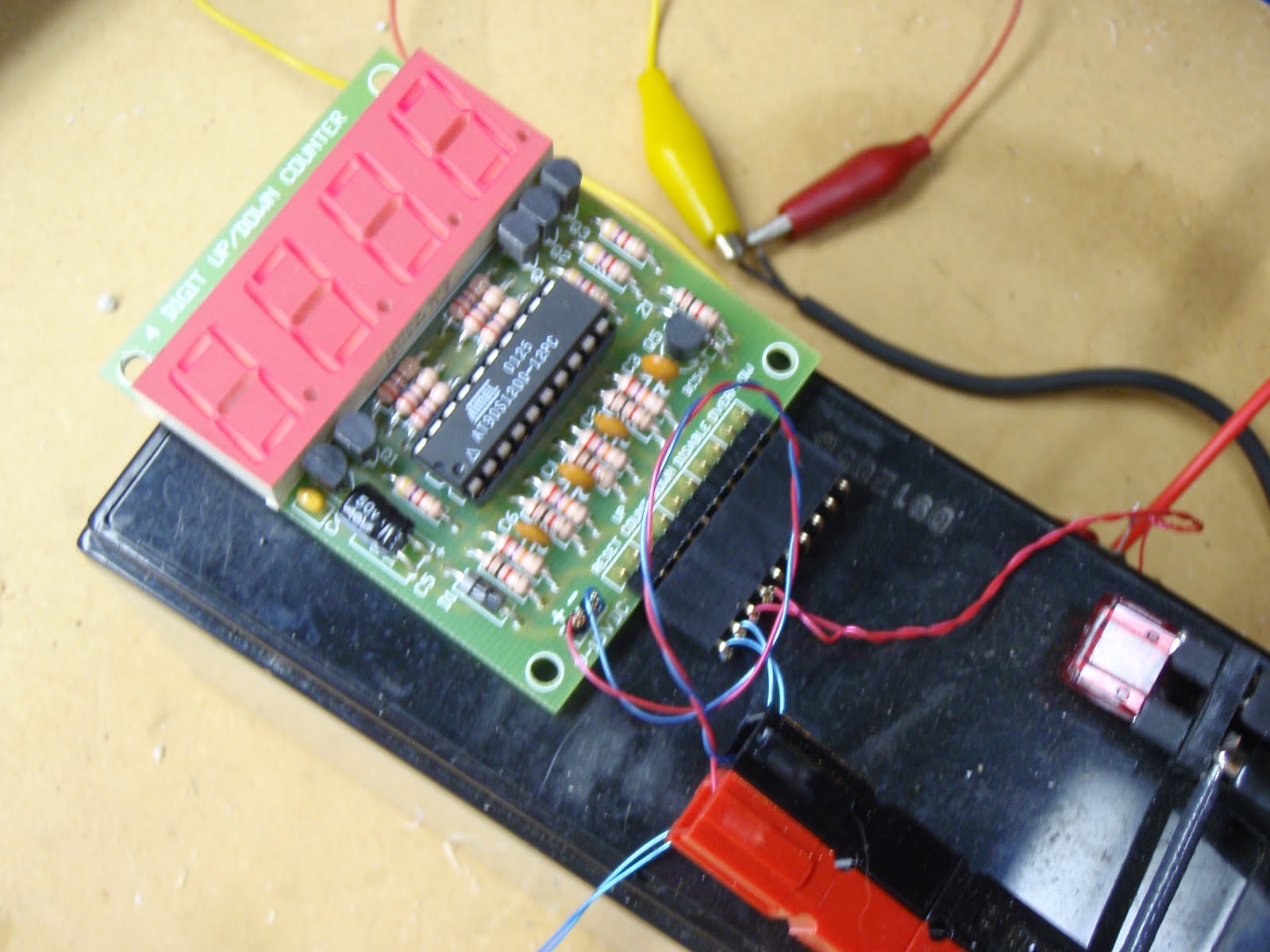
To count the turns, I used a digital event counter, triggered by a magnetic reed switch salvaged from a bicycle odometer. Every revolution of the form (and the magnet on the spring clamp) triggered the switch and would be counted. Crude but effective:

I purchased the magnet wire from Magnetic Sensor Systems in Van Nuys, CA. It's 25-gauge with nylon (SPN) insulation, rated to 155C, about $30 for 1000 feet. I had seen some cheaper 25-gauge magnet wire on the internet, but closer investigation revealed the insulation temp was only 105C -- and I didn't want to risk another thermal failure!


With a little care, it was easy to wind the coils using the motorized jig:


I kept an eye on the turns counter and stopped when it reached 158:


Here's one of the KB5WIA-wound coils next to one of the original Yaesu-wound coils. Not quite as beautiful as the one from the factory, but fully functional:


A quick QC check of coil resistance showed it to be 1.9 ohms, in the right ballpark:


Here are the four completed coils. In the background is the new magnet wire (red), and the spool of discarded Yaesu wire (gold):


The new coils slipped right onto the inner star-shaped lamination stack:


After all four coils were attached, I wrapped them in a half-width of Scotch 3M 33+ electrical tape:


Next it was time to begin re-stacking the laminations. Took about an hour to put the laminations back on, taking care to press each one down firmly and lock it into the one below.


I wondered how many laminations I'd be able to get back on to the motor -- since they were stacked so tightly to begin with, I was worried that deformations / air gaps would make the reassembled motor pretty ugly. In fact, all but one of the laminations (57 of 58 total) stacked on nicely:


I loosely threaded new red / green / black wire through the motor in the same manner as it was originally wound:


And then connected each of the four coils, and the three power wires, to the circuit board:


The next QC check was to measure the resistance of the four combined series windings, between the red and the green wires. I would expect around 7.5 ohms:


Testing showed the four coils measured out at 7.8 ohms -- close enough!


The motor is now ready for the assembly of the rotor and the end caps. There are around 5 flat washers on the rear end of the motor, and one flat washer on the front (drive) end of the motor:


Applying just 12VAC to the motor, it spun up nicely! Power to black+green spins one direction, black+red spins the other. The motor was very smooth and quiet:


Next it was time to reassemble the motor header and gear. The motor drives a wing secured with an allen screw, which then pushes against a thin steel spring riding in a nylon circle (the brake). On the other side of the spring tabs is a tang from the drive gear. Here are the components:


The wing was secured to the motor shaft. Correct position was a little of trial-and-error (adjusted so that the lock washer would snugly fit on the end of the drive shaft with the gear installed):


White lithium grease was added to the inside of the brake assembly:


And here is the motor attached to the header plate, with the wing secured to the shaft, and the brake assembly surrounding it. You can barely see the steel spring inside the white nylon circle that acts as the brake:


The drive gear was then attached to the shaft, between the two tabs of the brake spring. In this manner, the motor loosens the spring as it spins against the drive gear, but if the drive gear tries to turn the motor, it expands the spring and acts as a brake:


The motor header plate could then be attached to the gear cluster. Here is the gear cluster before the header is attached:


And here is the motor after affixing to the gear cluster:


Next step was to add the thermal protection switch and reconnect the wires to the limit switches, the run capacitor, and the power entry. The thermal switch is rated at 75C (so it will trip long before the wire insulation breaks down at 155C). The switch is in-line with the black (common) lead:


Here is the assembled motor and gear cluster with the thermal switch attached:


The motor and gear cluster is then reinserted into the lower rotator housing:


And the connector break-out allowed me to apply power to the motor for testing (right side, yellow leads) while monitoring the resistance of the 0-500 ohms position sensor (left side, red+black leads):


The system works nicely!


The next steps in reassembly are to re-grease the bearing races and ball bearings (using marine-grade grease), and the reassemble as shown in my previous post.

Overall, the motor repair was an interesting project, it was a lot of fun to take the totally non-functional unit apart and then reassemble it into something that works again!

For anyone interested in more rotator repair information, read on to see the assembly in the next post, or check out the following web links:

General Yaesu G-5500 rotator repair:
http://www.sunsunsun.net/kd4app/amsat/g5500.htm

Yaesu G-5500 elevation rotator repair:
http://ivok.home.xs4all.nl/pa1ivo/G-5500.html
http://www.ocrg.org/W7KKE/rotor/rotor.html

Monday, March 12, 2012

Az / El Antenna System - UHF Yagi and G5500 Thermal Switch


A few weeks ago I upgraded the Az / El satellite antennas in the backyard to a new UHF yagi. The previous Diamond A440-S15 antenna was working fine, but I wanted to try the M2 440-18 (18-element) yagi for slightly higher gain on UHF. The installation went well, but unfortunately the slightly longer antenna impacted the house roof as the array was rotating around to line up with a satellite pass. Oops!!


Turns out the drive motor in the Yaesu G5500 azimuth rotator had burnt out. Symptoms on disassembly were a burnt smell (obvious), along with a mismatch in coil resistance indicating that one of the coils had shorted from overheating. The coils are series-wound, and should be roughly 7 ohms total, or 3.5 ohms each (red to black, green to black should both be 3.5 ohms; red to green should be 7 ohms). My motor had one winding with only 1.0 ohm resistance, clearly shorted. I'm not sure how long the motor was stalled for, but probably for quite some time in order for the motor to heat to this point. Interestingly, the G5500 controller fuse did not blow - I found out later that the 24V AC motors used in this rotator draw pretty much the same current at free run, under load, and at stall. Therefore, even though I had previously installed the smallest fuse that would work under normal operation without blowing (1A as opposed to the factory-installed 2A fuse), the fuse never needed to blow to protect the controller. Instead, the motor simply overheated and shorted:


A quote for motor repair (rewinding) from a company in LA came to $365 -- about 3X what the motor costs new. Replacement motors are currently unavailable at Yaesu Parts (March 2012) due to supply issues from Yaesu Japan. In order to move things ahead, I decided to go ahead an purchase a complete G5500 system to use as a spare, and I could directly swap the azimuth rotator into the antenna array in the backyard.

Before I installed the new rotator, I disassembled it to install a thermal switch (cutoff point 75C). The thermal switch is wired in series with the black (common) lead to the motor, and is directly attached to the motor housing. This way, if the motor starts to go over-temperature, the thermal switch will cut power to the motor and prevent any overheat problems. Bench-testing indicates that the switch will shut off the motor after roughly 10-15 minutes continuous operation at 65F ambient temperature. I'll have to wait until summer (with air temps of 100F+ and solar heating of the rotator chassis) to see if there is enough margin in the thermal switch to keep it from cutting off too soon with normal operation ... I suspect a 100C switch might be a bit more useful.

Here's the process for installing the thermal switch:


The thermal switch is uninsulated, use heat-shrink tubing to insulate leads and body.


This process works for the Yaesu G5500:


Place a matchmark on the chassis for future reference:


IMPORTANT: do the following steps inside a box -- if you mess up, the ball bearings will go running 100 different directions at once!!

Flip the rotator upside down and remove the four bolts holding the lower bearing ring:


Grab the rotator, holding the lower bearing ring, and flip it upright. Carefully (!) lower the lower bearing ring and ball bearings down from the rotator. The ball bearings sit in a nice groove on the ring, as long as you keep the ring level the bearings will stay in place:


Now lift the rotator off of the lower bearing ring, taking care to grab the entire unit at once. Carefully invert the rotator and lay it upside down again:


Lift the rotator bottom straight up off of the rotator upper. The remaining bearings will stay inside the race inside the rotator upper. Be extremely careful to lift the rotator bottom level and sraight up, so you can note the position of the limit switch lever.


While continuing to lift the rotator straight up, carefully examine the position of the limit switch lever from underneath. Take note (!) of the orientation of the limit switch (towards the right lever or left):


Turn the rotator upside down again and set it down:


The internal motor and gear assembly can be pulled after removing the three bolts holding it on. Solder the thermal switch into the common (black) lead, and zip-tie the switch to the motor:


A close-up of the thermal switch. Note that heat-shrink tubing was used to insulate the body and leads:


Reassemble the rotator in reverse order, paying special attention to the position of the limit switch lever, and the match-marks on the rotator housing. Once reassembled, bench-test the rotator for normal operation:


Aligning the rotator halves from scratch, if the original positioning is lost for example, is not that difficult. The linear position sensor potentiometer has a 500-ohm range, of which 450 ohms is used during the 450 degrees of rotator travel. Therefore, the sensor changes by one ohm per degree of travel. Connect an ohmmeter to the sensor common and one of the sensor outputs and measure the resistance. While monitoring the resistance, run the motor for counterclockwise rotation of the rotator head. Check that the resistance goes down -- if it's going up as you rotate counterclockwise, you're monitoring the wrong sensor output and select the other one. Verify that your position monitoring is working: you should be able to run the assembly close to 0 degrees (ohms) counterclockwise, and close to 500 degrees (ohms) clockwise. Next, drive the gear assembly to the position where the resistance reads 65 ohms. (Setting the position at 65 ohms, and installing the rotator upper half in the 45 degree position, will give you 20 degrees clearance on the sensor below zero degrees rotation, and about 30 degrees of clearance past 450 degrees rotation.) Position the limit switch lever towards the right (looking at the rotator with the multi-pin connector facing you). To install the upper rotator half at 45 degrees, look at the upper rotator shell and locate the vertical matchmark on the outside rim. This matchmark will line up with a similar matchmark just above the 8-pin connector. Set the upper shell down on the lower housing such that the matchmarks line up as close as possible. At this point it helps to mark the protruding rectangular tabs on the upper housing with degree values: the one to the left of the matchmark is 0 degrees, the one to the right is 90 degrees, and so on. The rotator is now positioned at 45 degrees and the resistance from the sensor should read 65 ohms. Rotate the rotator counterclockwise and verify that the rotator comes to a stop at zero degrees; the resistance here will be around 20 ohms. At zero degrees, the tab you marked with "0" will be directly above the multi-pin connector. Next rotate the rotator clockwise and verify that it comes to a stop at 450 degrees; the resistance here will be around 470 ohms. The tab marked "90" will be directly above the multi-pin connector. Rotate the system back to a reading of 65 ohms and verify that the matchmarks line up. Alignment is complete.

And three weeks later, back on the satellites!

Saturday, January 21, 2012

January VHF Contest - Mt Diablo

January 21st was another ARRL VHF Contest, and I managed to spend a few hours at the summit of Mt Diablo (grid square CM97, elevation 3900') making contacts. The weather was cold and windy, and this year I used the Elk antenna for 70cm and 2m, and the HO Loop for the 6 meter band. Despite the cold, the contest was a lot of fun! The Buddipole mast worked well in the truck bed to support the antennas.


Sunday, January 1, 2012

ARISSat-1 Linear Transponder

The satellite ARISSat-1, launched from the International Space Station in July of 2011, is now literally in it's final days. Predictions are that it will de-orbit (aka burn up) around January 4th, just four days from now.


The satellite carries a linear transponder, capable of relaying uplink signals in the 70cm band to a downlink in the 2m band. Since the 70cm antenna on ARISSat-1 is missing, signals through the transponder aren't the greatest, and not many hams use this for two-way QSO's. I've called CQ occasionally for months now on the satellite, to only hear my own downlink and no one else in the passband. Fortunately, I was able to make a few QSOs in the last few weeks -- one SSB QSO with AI7W on 12/22/2011, and a CW QSO just yesterday with N6EV on 1/1/2012. It certainly is exciting to hear others on the satellite!!

Here are some screenshots from the last pass -- 1/1/2012 1848 UTC. The first shows SatPC32 and the footprint of the satellite as it approaches:


And the next screenshot shows a spectrogram of the downlink at 145.932 MHz. The white lines are my CQ calls in CW. They slope to the right due to the doppler shift of the satellite; as I transmit my uplink frequency stays fixed. You can even see how the slope of the traces gets steeper as time goes on (top of spectrogram is more recent), showing how the doppler shift gets even more significant as the satellite gets closer:


I called CQ in CW and SSB during the pass, and heard a faint SSB reply but couldn't make out the callsign and complete the QSO -- after the pass, however, I listened to my recording and could clearly hear KO6TH in CM98 calling me back! Near the end of the pass, I also heard someone tuning up in CW but signals faded out for me at that point.

Here's the location of ARISSat-1 as I lost the signal:


And the traces of my CW signal (still calling CQ at this point) as the satellite gets out of range: