This is an article based on recent experiences installing the FUNcube Pro+ receiver and MAP65 -- I had a lot of help from the W6YX team, and thought it might be useful to put together a how-to guide here in case any other hams wish to do the same. Enjoy! -Dave KB5WIA

SUMMARY
A software-defined receiver coupled with MAP65 software will allow the amateur radio EME (Earth-Moon-Earth) operator to visualize the entire EME sub-band at once. This can be a great benefit to both small and large stations, since monitoring the entire spectrum simultaneously will tell you exactly where other EME stations (strong enough for your system to decode) are located.
This article describes how to install a FUNcube Pro+ (FCDPP) software defined radio (SDR) into an exisiting EME station. It assumes that the operator is already familiar with EME exchanges using the JT65B protocol, has experience with WSJT software, and has basic EME station hardware.
HARDWARE
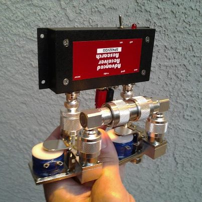
A typical EME-capable station will have a mast-mounted preamplifier, sequencer, and separate transmit and receive lines. For my 144 MHz EME, I use two M-Squared (M2) 2M7 antennas coupled with a M2 power divider, feeding an Advanced Receiver Research (ARR SP144VDG) GAsFet premplifier with +24dB gain. Received signal is sent through a separate receive coax (75' of RG-8/U) to a hybrid splitter combiner (ie. Mini-Circuits ZFSC 2-2 Power Splitter, 10-1000 MHz). The FunCube Dongle Pro+ is connected directly to the output of the splitter, the other port goes directly to the analog radio.
.jpg)
Appropriate coax relays are controlled by a dedicated sequencer and protect the mast-mounted preamplifier and switch between the separate TX/RX lines. I also found it helpful to add a dedicated coax relay to switch the input of the splitter to a 50-ohm dummy load during transmit; this also helps to prevent spurious JT65B decodes. The main hardware list is as follows:
- Antenna(s)
- Sequencer
- Mast-Mounted LNA
- A/B coaxial RF relay at mast (high-power)
- Separate RX / TX lines. RG-213 or RG-8/U is OK for RX side.
- High power amplifier
- A/B coaxial RF relay in shack (low-power)
- 2 port hybrid splitter
- SDR (in this case, the FUNcube Dongle Pro+)
- Traditional transceiver and WSJT9 software
- Multi-Core CPU (MAP65 is more CPU intensive than WSJT)
- Second 1080p monitor (optional, but recommended)
If separate transmit and receive lines are not used, careful attention needs to be placed on protecting the FCDPP receiver from damage during transmit. The configuration settings described below will likely need to be optimized if station hardware differs significantly from the above. It should, however, provide a good starting point.
COMPUTER SETTINGS
A reasonably fast computer is required, and both Linrad and MAP65 can consume a fair amount of memory. Modern multi-core processors should be fine. These instructions are written with the Windows 7 operating system in mind. It helps to disable power saving options on the computer used to run the SDR.
INSTALLING THE FUNCUBE DONGLE PRO PLUS
Read the user manual for the FUNcube Dongle Pro+ (FCDPP) and install the software according to directions. The main steps will be:
- Obtain documentation at http://www.funcubedongle.com/?page_id=1225
- Download FCHid
- Download SDRSharp
- Install both programs
- Verify the FCDPP demodulates signals
- Update the FCDPP firmware to latest
- Verify (again) the FCDPP demodulates signals
The FUNcube Dongle can be attached directly to the computer's USB port, but some operators have reported that it's better to use a short USB extension cable. This allows the FUNcube to be physically separated from the computer (reducing RF ingress) and also takes some of the strain off of the USB connector. I have not seen any RFI issues myself, but use a 3-foot USB extension cable with a ferrite core.

INSTALLING MAP65
Download and install MAP65 from Joe Taylor's website at http://www.physics.princeton.edu/pulsar/K1JT/map65.html. Comprehensive installation directions (and a great manual!) are included on Joe's webpage, just follow them step by step. Be sure to install to the path [C:\MAP65\].

INSTALLING LINRAD
This article was first written using Linrad 3.46, which is a good starting point and can be upgraded to current/future version as you gain more comfort and experience using Linrad. [1]
To start, I have backed up my entire Linrad 3.46 folder to the location http://zdap.com/radio/kb5wia_linrad_346.zip (The original Linrad 3.46 files are called "linrad.exe", "errors.lir" and "help.lir"). Download this file and unzip the contents. Make a folder called [C:\ham\linrad\linrad346_funcube_pp] and copy all of the individual files into this folder. All the files should be at this folder level, with no subfolders.
Optional: Download the Linrad DLL package from http://www.sm5bsz.com/linuxdsp/linrad.htm It's called "setup-linrad-dll-package-02.exe", and will install the necessary DLLs on your computer. Install the program as an Administrator. Note that in my experience, MAP65 installs the necessary DLL files automatically, so I have skipped this step. If the DLL's aren't installed, Linrad will tell you on start-up, and you can come back and do this step later.
Make a folder called [C:\linrad_data\].
The next instructions tell Linrad which USB port your FCD+ is plugged into. Note, you should always plug in the FCD+ into the exact same USB port, otherwise you'll have to follow all these steps again. ENTER
From [C:\ham\linrad\linrad346_funcube_pp\] start linrad.exe
From the start-up menu:
Verify that the top right-corner of the Linrad display says "Callback ExtIO_FCDPLUS_G0MJW". This tells you that Linrad has found the ExtIO DLL (that controls the FUNcube Dongle). If it does not, go back and double-check that your configuration files are in the Linrad directory.
Press U

Press A

Press F (LibextIO hardwares)
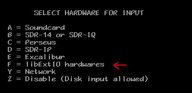
Press 0 ENTER (zero)

Press N ENTER

Press any key and wait 10 seconds

Press N when asked about port audio

Choose the sound card device number that corresponds to your FCD+. Say it's 2, then...

Press 2 ENTER

Press N ENTER

Press N ENTER

Type in 96000 ENTER

Press 2 ENTER

Type 0 ENTER

Type 0 ENTER

Even though it's not required for MAP65, the steps below will tells Linrad to send SDR from the audio to your speaker.
Press B

Press N

Choose the sound card device number that corresponds to the soundcard your PC speakers are connected to. Say it's 0, then you'll type 0 ENTER.

Follow these next steps otherwise nothing you just did will be saved:
Press X
Press X

Press any key
Press W (on the main menu to actually save the settings)

Now press Escape to close Linrad and restart Linrad.
From now on, you only need to press "D" to put Linrad in SSB mode. You can type in your center frequency on the top right corner to tune the FCD+. 144.130 is good. This also controls the center frequency in MAP65.

You can now minimize Linrad and not worry about it. Press "ESC" on Linrad to close the program when you're ready to shut it down.


If you want to learn more about Linrad, Leif SM5BSZ has lots of information on his website at http://www.sm5bsz.com/linuxdsp/usage/newco/newcomer.htm. You can also hover your mouse over any part of the Linrad screen and press F1 to bring up a helpful description of what that control does.
If everything works, make a backup of your [C:\ham\linrad\linrad346_funcube_pp\] folder for when (not if) you screw up a Linrad setting and can't fix it. To revert to your backup, simply copy the files back to the same location.
CONFIGURING THE FUNCUBE DONGLE PRO+
Initial defaults for the FCDPP hardware settings seem to be optimal. LNA is ON, Mixer Gain is HIGH, IF Gain is 0dB, and frequency correction is 0.96ppm [2]. The Bias T should be off, assuming that you're not powering the preamp through the coax.

Note that the FCDPP is a different device than the original FUNcube Dongle Pro. Those original units used a different tuner chip, with a different ExtIO control panel. On the original, the optimal settings for EME were 20-30dB of LNA gain and 4dB mixer gain, with all of the following stages set to their lowest gain value. The original also needed a tight bandpass filter in front of the FCDP, and some sort of thermal stabilization to prevent frequency drift.
A narrow bandpass filter on the FUNcube Dongle Pro Plus is automatically selected on the 2-meter band. Howard has redesigned the Pro+ model of the FUNcube to have a fairly tight SAW filter in the front end, which greatly limits the out-of-band sensitivity problems seen in earlier versions. That being said, you may wish to experiment with a narrow bandpass filter in the receive line if you suspect out-of-band interference problems. For me, a 2-pole helical filter ahead of the FCDPP does not change performance significantly, the FCDPP’s internal bandpass filter is sufficient.
CONFIGURING LINRAD
Download, print, and review the following PDF files, they tell you what many basic Linrad screen controls do:
http://vhfdx.radiocorner.net/pics/LinradScreen1.pdf
http://physics.princeton.edu/pulsar/K1JT/Linrad_On-Screen_Controls.pdf
Adjust the FFT1 Amplitude (this is the equivalent of the front-end gain in Linrad) to a value of "100". This will prevent the FCDPP from over-driving Linrad and causing a white or pink waterfall display.
- Start Linrad
- Press "D" to enter SSB Mode.
- Press "X" to change settings.
- Press "P" to change parameters.
- Change the value of FFT1 Amplitude to "100".
- Press
- Click Continue to reach the end of the parameter menu.
In the same manner as above, I have also changed the First Backward FFT Version from "1" to "0". This tells Linrad to send 32-bit floating point data to MAP65, rather than processed 16-bit data. I'm not sure of any performance difference with this setting, but at present it makes sense to send all of Linrad's data to MAP65. I've also changed AFC/SPUR/DECODE to "0", since I have found that the auto-spur reduction does not impact the MAP65 waterfall. The ssb config settings I currently use are below. [4]


Disable the strong signal blanking on the MAP65 output. This step is optional; in my environment, I don't have strong signals within the FCDPP passband. In the lower left box that says [500][10][1] (or similar) change the right-hand value to "1".

Turn on and adjust the Dumb Noise Blanker (NB). (It's called the "Dumb" blanker to differentiate it from Linrad's "Smart" blanker.) Optimal NB settings will depend on what type of local noise you have. Try starting at 5% blanking, and then adjust upwards or downwards on actual JT65B signals over many decodes to see if a higher or lower value works better.
- In the box on the lower left of the high resolution spectrum, choose "A".
- Grab the yellow bar to the right of the bar graph underneath the high resolution spectrum.
- Drag the yellow bar back and forth until the box in the upper left of the graph shows "5".
- This sets the Noise Blanker to Automatic and blanking 5% of signals.

CONFIGURING MAP65
Start MAP65 and verify that it's receiving data from Linrad. You can tell that it's receiving data because the signal bar graph on the left side will turn green, and will be showing some sort of amplitude.

If MAP65 isn't receiving data, make sure it is set to receive data from Network, use port 50004, is set for 96000 Hz sampling, etc.

Verify your noise floor. On my system, at this point, the noise floor on MAP65 will fluctuate around +23dB with antennas pointed away from noise sources into a cold sky. It's also normal to see the noise levels go up by +8dB when the antennas are pointed towards the horizon in a suburban environment.
Verify your preamp is functioning. Turn off the mast-mounted preamplifier and verify that the noise floor drops significantly (at least 10dB, preferrably 20dB). On my system, the noise floor drops to around +7dB when power to the external +24dB preamplifer is removed.
Adjust the NAvg on MAP65 to a value of 10, so that 1 minute of time corresponds to approximately 1cm of vertical space on the waterfall. Averaging the lines (a slower waterfall) will help you see weak traces.

Zero the MAP65 waterfall brightness. After zeroing, the waterfall should be a blue color. I'll typically zero the waterfall with antennas pointed at the cold sky, so the color of the MAP65 waterfall can tell me how much local noise I'm seeing at any point in time: Blue = nice and quiet; Green = Marginal; Orange and Red = only the big guns will get through!
Increase the gain on the MAP65 waterfall to 5 or so to get more "snow". This will help you visualize weak traces better.
Don't run MAP65's noise blanker since Linrad's noise blanker is turned on.
Verify the frequency display is correct. Look for a birdie (or set of birdies) on the MAP65 wide screen waterfall. Take a note of the frequencies, then tune your analog radio to the same frequency. Verify that you can see the same birdies on both radios. On my system, they are pretty close, about 40Hz apart.
Configure the MAP65 output to your analog radio (transmitter). You'll need to specify the sound card output, and the COM port used to key the PTT line. These should be the same settings that you are using in WSJT9 software. Try calling CQ on an open frequency and verify that the MAP65 transmissions and levels seem correct.

IMPORTANT: Update MAP65's call3.txt. Download the latest from http://www.mmmonvhf.de. The program WSJTMerge from http://www.k2txb.com/WsjtMerge.htm can be used to merge an existing call3.txt file with the new one. Also, if you're not in the Make More Miles on VHF Database http://www.mmmonvhf.de/dbase.php already, then you're potentially missing out on +4dB of coding gain because other EME stations may not have you in their own call3.txt files. Be sure your call is in the call3.txt from this site. It's difficult to stress how important this is -- if you're a small station, and you're not in the other station's call3.txt file, it's going to be much, much more difficult to have a QSO.
Make sure to turn on aggressive deep search in MAP65.
MAP65 has a Setup option to reduce the font size in the Astronomical Data window. Set it to something like 12 or 14 pt so you can see everything in the window.
USING THE SYSTEM
By now you have a system that is decoding JT65B signals on two separate radios: the FCDPP and your traditional analog radio. With the settings described above, the FUNcube Dongle Pro Plus should be about the same sensitivity (able to decode JT65B signals about as well) as your analog radio.

By running both MAP65 and WSJT9 simultaneously, you now have an even better ability to decode signals on the frequency you're looking at. For example, if one of the two radios misses a decode (random noise, etc), the other one may pick it up. You can also use one radio to check on the decodes of the other -- for example, seeing both radios decode the same message virtually rules out the chance of a false decode.
Moreover, you can now visualize the entire EME sub-band on the MAP65 waterfall, so you can quickly check other frequencies for active EME activity. Even better, MAP65 has the band map / message list, and will decode stations that you're not even looking for (albeit, with slightly reduced sensitivity).

Importantly, using MAP65 you're no longer limited to finding stations calling CQ on the internet chat rooms. You'll find stations that *your* station can hear, since by definition MAP65 is only going to report to you the stations that you're capable of receiving. As a bonus, you can also quickly use MAP65, which displays the last 5-10 minutes of spectrum activity, to zero in on a station that you saw calling CQ in an internet chat room to see if you can find any traces of signal.
You can also use the two radio systems (analog and digital) for optimizing one or the other. For example, you can experiment with different Linrad settings, or different filters, on the SDR side and make A/B comparisons with the decoding on the analog side. Given the high degree of variability of EME decodes, having a direct A/B comparison greatly improves your ability to optimize one or the other.
Overall, the incorporation of an SDR and MAP65 into your station should greatly enhance your ability to make EME contacts, even with a smaller station.
OPTIONAL: INSTALLING HDSDR
The HDSDR program can also use the FCDPP as a regular receiver, and has a very nice user interface. I use HDSDR to monitor the entire VHF passband of U/V satellites (ie. VO-52, AO-07). Make a folder called [C:\ham\hdsdr]. Download HDSDR http://www.hdsdr.de/ and install into this folder. Also download the FCDPP ExtIO files from the Hardware page on the HDSDR site, and place them into the [C:\ham\hdsdr] folder.
ACKNOWLEDGEMENTS
Much assistance from the W6YX team is appreciated with regards to getting this system working!
REFERENCES AND NOTES
[1] Alternatively, install Linrad from scratch. Linrad can be downloaded from http://www.sm5bsz.com/linuxdsp/linrad.htm, and installation instructions are on the same page. The necessary FUNcube Dongle Pro+ ExtIO DLL and INI files can be downloaded from the HDSDR page at http://www.hdsdr.de/hardware.html. The DLL and INI files need to be located in the same folder as linrad.exe.
When it comes time to upgrade your Linrad, the steps are basically a) to copy your current Linrad folder to a new one with a new version name. b) download the latest Linrad exe and dll files from the website listed above. c) Start Linrad and if there are any errors (ie. ssb configuration settings mismatching), open your old configuration file (such as par_ssb.ini) and enter the configuration settings into the new version.
[2] You can also run the FCDPP with LNA = ON and Mixer Gain = Low if you need extra dynamic range or linearity. If you do so, you'll need to adjust Linrad's 1st FFT Amplitude value to around 500 in order to compensate for the reduced FCDPP gain. This alternative setting seems to result in fewer MAP65 decodes, and generally (ca. -2dB)s/n values, but your mileage may vary.
[3] MAP65 seems to work well with a wide input range, but try to keep it in the +20 to +30dB range. In my own experience, input levels above +40dB cause significantly reduced decodes.
[4] With the settings I'm currently using, Linrad+MAP65 can decode just as well as my Yaseu FT-817ND transceiver with WSJT9 software in the range of -25dB and better signals. For extremely faint signals in the range between -30dB and -25dB, the analog WSJT9 system seems to have better performance at decoding traces. Whether Linrad+MAP65 can be adjusted to perform even better remains to be seen. There are many factors that can be adjusted in Linrad, and what I have here is a starting point. It will be interesting to see what the ultimate consensus is on "best" settings for these softwares.
[5] Ordering a FUNcube Dongle Pro Plus: Howard Long G6LVB has ordering instructions on his website at http://www.funcubedongle.com/, look for the tab called "The New FUNcube Dongle Pro+", you can find out about how to order it right there. When I ordered mine, there was a waiting list of a few weeks -- put in your name and Howard will send you an email telling you when yours is ready to order. Pricing is on the website also, and proceeds from these units go to AMSAT-UK's FUNcube satellite project, so it's also for a very good cause.
[6] Further Support: There is a good Google Group for Linrad that also has quite a bit of MAP65 information. The FUNCube Pro Plus has a Yahoo Group in the UK at http://uk.groups.yahoo.com/group/Fcdproplus/.
[7] A word about direct connection between MAP65 and the FUNcube Dongle Pro+. The current version of the MAP65 program (2.4.1) provides support for the FUNcube Dongle Pro, but this does not support the Plus (+) version that came out in October of 2012. Some of the current information on the internet can be confusing, because it was written before the advent of the Pro+ receiver.
If you have an older FUNcube Dongle Pro version (pre-October 2012), then you can either run MAP65 v. 2.4.1 direct, or you can follow the instructions above and use Linrad -- but if you do, you'll need to use a different ExtIO program. The ExtIO for the older Pro can be downloaded from the HDSDR page as described above. I haven't tested this, but there are others who use the Pro > Linrad > MAP65 system via this route. Keep in mind that the Pro does not contain the high-stability TCXO or the tight bandpass filters of the Pro+: Other EME operators have found that it's essential to use an external tight bandpass filter between the LNA and the FCDP, and also to wrap the unit in a towel to maintain temperature and reduce thermal frequency drift. Both of these issues are solved with the newer FUNCube Dongle Pro+.
It is also reportedly possible to run MAP65 directly with the FUNcube Dongle Pro+, bypassing Linrad as described here. The problem is that MAP65 v2.4.1 does not provide a control panel for the FCDPP. It does, however, accept the direct sound card input that the FCDPP provides. To control the FCDPP, those that run MAP65 direct seem to use the FCDPP FCHid program as a substitute for Linrad. This program can be downloaded as described in the Pro+ manual (http://www.funcubedongle.com/MyImages/FCD2ManualV3.pdf). In addition, the MAP65 frequency must be manually forced to the same freq as set in the FCHid program; this is because the sound card data does not carry the frequency information. I do not use this method, since I have had no issues with Linrad as an intermediary. Linrad allows for much experimentation with the SDR settings, and also provides a great learning opportunity to better understand how software-defined-radio works.


.jpg)