Monday, December 31, 2012

EME System Optimization

Now that I'm using the dual receivers for EME, it's time to optimize performance to get the most out of the small antenna system that I'm using.


SYSTEM
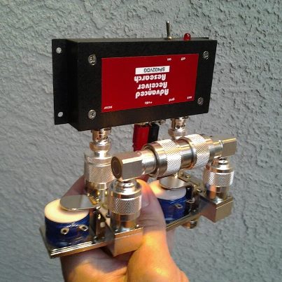
The two M2 2M7 antennas feed directly into an Advanced Receiver Research SP144VDG GasFET preamplifier (24dB gain, NF=0.5dB) on the mast, which then sends the RX signal down 75 feet of RG-8/U coax to a 50-ohm hybrid splitter/combiner in the shack.  One port of the hybrid feeds the FunCube Dongle Pro Plus (FCDPP) software defined radio (SDR), the other side feeds the Yaesu FT-817ND conventional radio with intalled TXCO.  The FCDPP sends signal to Linrad which sends signal to MAP65 software.  The FT817ND sends signal through the computer's soundcard to WSJT9 software.

ANALOG RADIO
The Yaesu FT-817ND seems fairly well optimized for weak-signal VHF detection right out of the box.  I use settings of Noise Blanker (NB) = ON, Automatic Gain Control (AGC) = OFF, and RF Gain set to a reading of about S2 on the S-meter (equivalent to roughly a 2 to 3 dB reduction in RF gain from max).  The interface box between the FT-817ND and the computer's microphone input jack is adjusted so that Windows sees about 2 "bars" of signal on the microphone levels.   I arrived at these settings by empirically watching weak signals on the WSJT9 waterfall display and optimizing for best visual signals.  It's subtle -- there's not much difference between out-of-box defaults (AGC On, RF Gain Max) and these settings, both seem to work well, but in my location (suburban RF noise) having AGC off seems to allow the WSJT9 software to see fainter traces through the noise.

SOFTWARE-DEFINED RADIO
The FunCube Dongle Pro + is a completely different SDR than the original FunCube Dongle or Funcube Dongle Pro.   It contains an entirely different tuner chip, it has an embedded TXCO, and it has a front-end SAW filter for the 2m band.  Published settings for the FCD/FCDP with Linrad and MAP65 won't work directly with the FCDPP because the control interface is different.  Rather than having variable control of the LNA and Mixer gains, the FCDPP has two settings for the LNA (ON and OFF) and two settings for the Mixer (LOW and HIGH).  The ExtIO package that I'm using (from HDSDR) has LNA ON and Mixer HIGH by default.  Comparing different settings on the FCDPP and watching the waterfall display for weak traces, it seems that the combination of LNA ON and Mixer HIGH (=default) gives the best visual appearance of faint traces.  Turning the LNA off or the Mixer to low causes very faint traces to disappear into the background noise.

LINRAD SETTINGS
Linrad samples the FunCube Dongle Pro Plus at 96000 Hz.  I found that I needed to reduce the "front-end gain" of of Linrad in order to have the relatively high signal levels from the FCDPP not saturate the Linrad waterfall (settings above with Linrad defaults can lead to more than 40dB signals).  By reducing Linrad's FFT1 Amplitude value from the default of 1000 (or 500) to 100, the signals from the FCDPP with antennas pointed into a quiet sky are a more reasonable +22dB or so.  At present, I have Linrad also set with AFC disabled, Strong Signal Removal "1" (=off), MAP65 Attenuation -15dB, and the "dumb" noise blanker (NB) set to blank about 5% of the incoming signals.

MAP65 SETTINGS
Linrad feeds the I/Q data stream to MAP65 via port 50004 at 96000 Hz, and with these settings MAP65 has a reasonable signal input level (around 23dB cold sky).  Turning the mast-mounted preamplifier off reduces the noise level by around 22dB.  Interestingly, before I turned Linrad's FFT1 front end gain down, the high incoming signals (about 43dB on MAP65) resulted in visually nice signals but almost no decodes!  Joe K1JT recommends to keep MAP65 input signals between 20dB and 30dB, and this seems to be very important.

ALTERNATE CONFIGURATION
(Side note: I've also used the FCDPP setting LNA=ON Mixer=LOW with Linrad FFT1 Attenuation 500, and while this achieves a similar end-result in the dB value sent to MAP65 (about 20dB cold sky), traces aren't as visually prominent, and decodes are a little spotty compared to WSJT9 with the FT817ND.  Moreover, in this other configuration, turning the mast-mounted preamplifer off reduces MAP65 noise by only 10-12 dB, which allows relatively more system noise to enter the noise factor equation.)

COMPARISONS BETWEEN SYSTEMS
Initial direct comparison of incoming EME signals indicates that the two systems (WSJT9/FT817ND and MAP65/FunCube Dongle Pro+) are pretty much identical in terms of sensitivity.  Over 26 full messages decoded, the two systems were very close in reported S/N dB values:  MAP65 had, on average, a 0.65 dB worse S/N reading, with a standard deviation of just over 1.0.  For 9 shorthand messages, MAP65 had an average of 2.50 dB better S/N reading, with a SD of 1.5.  Interestingly, the MAP65 system decoded 9 messages that WSJT9 did not decode, as opposed to only 2 messages that WSJT9 decoded that MAP65 missed.  Most of these missed by the WSJT9 system were shorthand messages.


SUMMARY
Overall, it seems that the peformance of the MAP65 + Linrad + FunCube Dongle Pro Plus system is virtually identical to the WSJT9 + FT817ND system.  The advantage of the MAP65 system, of course, is that the FunCube Dongle Pro+ sees the entire EME sub-band at once, and MAP65 can automatically decode messages found anywhere across the band!  This seems to be a real help in small-station EME, since  the software can automatically find stations that are strong enough for my antennas to hear.


Saturday, December 22, 2012

EME Upgrade - Separate Receive Line

This last weekend I upgraded the EME / Satellite station by adding a separate receive line to the 2-meter antenna array. This means that the system will now use a dedicated RG-8U line exclusively for receive (the transmit side uses LMR-600). The new system block diagram is below.


Splitting the transmit and receive lines enables the incorporation of a second dedicated receive-only radio into the system. For this, I'm using the FunCube Dongle Pro Plus, a 160MHz to GHz wideband software-defined radio (SDR). This SDR is about the size of a USB thumb-drive, and directly translates radio signals from the SMA port on one end to the USB connector on the other. From there, all the subsequent processing is done within the computer: the IF stages, mixers, and demodulators are all done in software instead of hardware.   The SDR is connected directly to the output of the hybrid splitter/combiner, which in turn is directly connected to the CX520 relay which switches between the RX line and a 50-ohm load.  This relay is important to prevent overloading the radios with signals coupled during transmit.


The SDR allows for all sorts of interesting things. It can monitor an entire satellite sub-band at once. For EME, it can monitor all conversations in the 144.100 to 144.160 MHz EME sub-band simultaneously. Since EME signals are extremely weak and almost impossible to hear by ear, having the computer search the entire sub-band for signals will greatly speed up the time to find an active station on the band. I'm running the SDR with Linrad software do do the initial filtering and processing of the wideband data stream, then MAP65 for decoding the JT65B signals reflected from the moon.


With the split receive, the JT65B signals can be decoded both by the traditional FT-817ND radio running WSJT9 software, as well as the SDR running MAP65. An example screenshot showing both softwares running simultaneously is shown above.  It leads to a lot of open windows on the computer, but it's really interesting to watch!

Monday, October 22, 2012

EME Upgrade


I've been upgrading my station to improve EME (earth-moon-earth) capabilities. Many components of the station are already set for EME -- since I work the satellites primarily, I already have the azimuth-elevation rotator (a Yaesu G5500), yagi antennas (18 elements on 70cm and 7 elements on 2m), computer control, and computer sound-card interfacing with the radios. This has allowed me to run the WSJT software in JT65B mode and copy some of the stronger signals reflected from the moon, and make a partial contact with K5GW in Texas last year. The goal this year is to produce a higher uplink power, as well as have improved gain and sensitivity in the antennas. A key aspect was to not have the EME upgrade interfere with the existing satellite capability.


For now, I'm focusing on the 2-meter band (144.105 to 144.150 MHz). It's challenging because of high local noise in that band, but there are more EME stations on 2m than the other bands combined. Here's a rundown of the station upgrades:

12V DC Power
I've upgraded to an Astron RS-70M power supply, that can put out up to 70 amps at 13.8 volts DC. I've also been working on a surplus computer server power supply (JD-200) that can produce 110 amps, but the supply generates a fair amount of RFI so that will be a longer-term project.


300 Watt Output
I'm borrowing a 300-watt amplifier from WB6EBR. By feeding a 5-watt signal from the FT-817ND radio into a RF-Concepts 2-23 amplifier, the signal is boosted to around 35 watts. The 35 watts directly feeds a Mirage 5030 amplifier, which will output close to 300 watts at this drive level.


Cooling Fans
The amplifiers and the radio can generate quite a bit of heat during the long (50-second) transmit periods and high duty cycle (50%) that the JT65B mode uses. A 6-inch cooling fan sits above the Mirage amplifier to keep it cool, and a 4" cooling fan sits behind the FT-817ND radio to cool it. Temperatures without the fan reach > 120F after 10 minutes, with the fans temps are kept to around 85F or so.

Frequency Stability
As the long transmit cycles generate more heat in the radio, the default crystal oscillator drifts slightly in frequency as the system warms up. The drift is around 5 to 10 Hz per minute, which is enough to interfere with proper decoding of the very-tight tolerance JT65B signals. I replaced the stock oscillator in the FT-817ND with a Yaesu TXCO-9 temperature-compensated crystal oscillator, that has much better improved frequency stability. This reduces drift, and will help in decoding very weak signals.


Preamplifier Bypass
The VHF preamplifier at the antenna is rated to tolerate 25 watts of RF transmit power, and would quickly be destroyed by the 300-watt amplifier during transmit. To protect the preamplifier, two Tohtsu CX-520D coaxial relays surround the preamplifier in a bypass configuration. By default, with now power, the relays allow the antenna to be connected directly to the amplifier, with the input/output of the preamplifier grounded. When energized,the relays switch input/output connections to allow the antenna to be connected to the preamp, and the preamp to the radio. The bypass relays are de-energized during transmit cycles to protect the preamp.


Sequencer
When high-power transmittion is initiated from the computer control, a series of events needs to happen in a specific order. First, the preamplifier must be shut down. Next, the bypass relays around the preamplifier must switch to connect the antenna directly to the high-power amplifier and bypass the preamp. After that, the high-power amplifier can be turned on. Lastly, the radio can be allowed to produce transmit power. I built a sequencer to control these events with a specific order and timing -- first prototyped on a breadboard using a core schematic from the internet, then assembled with discrete components onto a perfboard. On the transmit signal from the computer, the FT-817ND grounds a TX pin at the rear of the radio. This is detected by the sequencer, which then charges a 10 uF capacitor. As the capacitor charges, the voltage is compared to a reference voltage divider network at four voltages (channels), and as each threshold is crossed a trigger is sent to close a relay. Relay #1 removes power from the preamplifier on the mast. Relay #2 removes power from the bypass relays putting them in safe mode. Relay #3 sends a ground signal to enable the high-power amplifier. Relay #4 releases the TX Inhibit signal on the FT-817ND radio allowing it to transmit. The four relays close in order, with a delay of around 150 milliseconds each.


Stacked Antennas
To improve transmit gain as well as receive sensitivity, I added a second M-squared 2M7 yagi antenna. Previously I had the 70cm antenna on one side of the rotator cross-boom, and the 2m antenna on the other. In the new configuration, the two 2M7 antennas are vertically mounted on either end of the crossboom (separated by 6 feet 8 inches), and the UHF yagi is mounted horizontally above the rotator. Power is transmitted to both 2m antennas via a M-squared power divider and phasing harness.


Initial Results
The day after assembling the power supply, amplifier, relays, and sequencer system (it took about 3 weeks to get this all together), I was able to make quick contact with HB9Q in Switzerland via moonbounce. During that QSO two other stations (in Great Britain and Mexico) reported seeing my signals also. This was my first confirmed EME contact, woohoo! At this time I haven't tested the additional 2m antenna.

The photos below show the WSJT software screenshots from the QSO, as well as the antenna of the other station -- lots of gain there!


Here is my first EME QSL card -- pretty exciting to get the paper confirmation of a 2-way contact via signals reflected from the moon!!

Monday, August 6, 2012

ARRL UHF Contest - Mt Vaca


This weekend I spent a few hours in the ARRL August UHF Contest. The contest ran from 11am PT on Saturday, August 4th to 11am on Sunday. On Saturday afternoon, I drove to near the summit of Mt Vaca, located just west of Vacaville, California. The summit is at close to 3,000' elevation, and is at the end of a 6-mile road up from the valley below. The road continues north along the ridgeline, and I found a good spot with reasonable views to the north, east, and south.

For equipment, I used the Diamond 15-element UHF yagi, an ARR SP432VDG preamplifier, and the truck's Yaesu FT-857D radio (20 watts on UHF). The first few calls had very weak return signals, and a quick check confirmed that the preamp has burnt out (how did THAT happen??). I disconnected the preamp, and ran the yagi direct from the '857.

Weather conditions were great -- clear and sunny with almost no wind. I operated on 432.1 for about 2.5 hours, and in that time managed to make a total of 8 contacts -- pretty much everyone who was on the band in the Bay Area at that time! Signals with the yagi (my first time using a high-gain antenna during a contest) were very strong. A station on Mt Diablo (about 30 miles away) was S9+. A station above Lake Tahoe (100 miles away) was S7. Overall, the contest was pretty quiet, once everyone had worked everyone else, all we could do is wait for someone new to join in.

After the contest, I operated as a rover (KB5WIA/R) and provided a few more contacts in CM88 and CM98 grids.

Saturday, June 30, 2012

2012 June VHF Contest - Mt Diablo

The 2012 ARRL June VHF contest was a lot of fun again this year! As in 2011, I camped near the summit of Mt Diablo (grid square CM97) and operated solar-QRP portable. The equipment consisted of a 20W PowerFilm flexible solar panel powering a 6.4 Ah LiFePO4 battery, which powered the Yaesu FT-817ND QRP radio. My antennas were a 6m HO-Loop from M-Squared, and a 2m/70cm dual-band log periodic from Elk.

I started the contest around 1pm on Saturday, and kept going to about 8:30pm (sunset) Saturday night. Sunday I operated from around 7am to 8pm, the end of the contest. Conditions were pretty good -- other than some very strong winds, the temperature was pretty nice. Radio-wise, there seemed to be a few more stations out this year than last, and there were a few brief band openings on the 6-meter band.

 Overall, I made 249 contacts on the three bands (excluding duplicates), working a few dozen grid squares in the process. Lots of fun!

Thursday, March 29, 2012

Yaesu G5500 Rotator Motor Repair

As described in an earlier post, a few weeks ago I burnt out the azimuth portion of my Yaesu G-5500 rotator (similar to a G-5400) after the antenna array accidentally hit the rooftop. Yaesu USA parts currently (March 2012) has no replacement motors in stock (typically around $130), and a professional motor rewinding company quoted $360 to rewind the motor.

I decided to rewind the motor myself. The whole process was actually very straighforward, if somewhat tedious and time-consuming (about 10 hours work), but it was a lot of fun taking the motor apart then rebuilding it. The following photos show the steps in the process.

Here's the disassembled motor, with the end-caps and rotor removed:


The rear of the motor board, with the circuit board attached. The wires normally go though an insulated hole in the end-caps:


The front of the motor, note how the red/green/black wires wrap around the coils:


The circuit board:


With the circuit board removed, it's easy to directly measure the individual coil resistance:


0.4 ohms -- yep, it's certainly shorted!!


In order to get the coils out, the individual motor laminations need to be removed one-by-one. It's a tedious process, and took about 2 hours. There are 58 laminations. I marked diagonal lines on the outside of the stack to aid in reassembly, and also numbered each lamination as it was removed. They're on there pretty tight, and each one needs to be pried off:


Close to having all the laminations removed -- you can see the individual coils clearly now:


Yay! All 58 laminations removed and stacked separately:


The coils are protected by black tape which is easily removed:


And the four coils easily pull off the star-shaped inner lamination stack.


Each coil is about 2" x 1", and contains 158 turns of a single wire 620" long:


The wire from each coil weighs 22.0 grams. This equates to 0.932 lb / 1000', or about 25-gauge. I also measured the resistance of the wire (about 1.8 ohms), which also equates to around 25-gauge. Finally I measured the wire with a micrometer, and the diameter (about 0.0179") confirmed it's 25-gauge wire.


Here's my master drawing of the circuit board and wiring connections. It was very important for being able to connect the coils and power cables back correctly:


My winding jig was ugly but practical -- it consisted of a variable-speed drill controlled by a home-made foot pedal:


The drill chuck held a wooden form that neatly fit inside the center of the square coil windings. One one side of the form is a spring clamp that holds a magnet:


The empty coil housing shown here slips over the top of the wooden form. Two of the four coils were shorted, and the overheating had fused the insulation in the windings. The wire still pulled off of the housing fairly easily, and the housing itself was not damaged at all:


To count the turns, I used a digital event counter, triggered by a magnetic reed switch salvaged from a bicycle odometer. Every revolution of the form (and the magnet on the spring clamp) triggered the switch and would be counted. Crude but effective:


I purchased the magnet wire from Magnetic Sensor Systems in Van Nuys, CA. It's 25-gauge with nylon (SPN) insulation, rated to 155C, about $30 for 1000 feet. I had seen some cheaper 25-gauge magnet wire on the internet, but closer investigation revealed the insulation temp was only 105C -- and I didn't want to risk another thermal failure!


With a little care, it was easy to wind the coils using the motorized jig:


I kept an eye on the turns counter and stopped when it reached 158:


Here's one of the KB5WIA-wound coils next to one of the original Yaesu-wound coils. Not quite as beautiful as the one from the factory, but fully functional:


A quick QC check of coil resistance showed it to be 1.9 ohms, in the right ballpark:


Here are the four completed coils. In the background is the new magnet wire (red), and the spool of discarded Yaesu wire (gold):


The new coils slipped right onto the inner star-shaped lamination stack:


After all four coils were attached, I wrapped them in a half-width of Scotch 3M 33+ electrical tape:


Next it was time to begin re-stacking the laminations. Took about an hour to put the laminations back on, taking care to press each one down firmly and lock it into the one below.


I wondered how many laminations I'd be able to get back on to the motor -- since they were stacked so tightly to begin with, I was worried that deformations / air gaps would make the reassembled motor pretty ugly. In fact, all but one of the laminations (57 of 58 total) stacked on nicely:


I loosely threaded new red / green / black wire through the motor in the same manner as it was originally wound:


And then connected each of the four coils, and the three power wires, to the circuit board:


The next QC check was to measure the resistance of the four combined series windings, between the red and the green wires. I would expect around 7.5 ohms:


Testing showed the four coils measured out at 7.8 ohms -- close enough!


The motor is now ready for the assembly of the rotor and the end caps. There are around 5 flat washers on the rear end of the motor, and one flat washer on the front (drive) end of the motor:


Applying just 12VAC to the motor, it spun up nicely! Power to black+green spins one direction, black+red spins the other. The motor was very smooth and quiet:


Next it was time to reassemble the motor header and gear. The motor drives a wing secured with an allen screw, which then pushes against a thin steel spring riding in a nylon circle (the brake). On the other side of the spring tabs is a tang from the drive gear. Here are the components:


The wing was secured to the motor shaft. Correct position was a little of trial-and-error (adjusted so that the lock washer would snugly fit on the end of the drive shaft with the gear installed):


White lithium grease was added to the inside of the brake assembly:


And here is the motor attached to the header plate, with the wing secured to the shaft, and the brake assembly surrounding it. You can barely see the steel spring inside the white nylon circle that acts as the brake:


The drive gear was then attached to the shaft, between the two tabs of the brake spring. In this manner, the motor loosens the spring as it spins against the drive gear, but if the drive gear tries to turn the motor, it expands the spring and acts as a brake:


The motor header plate could then be attached to the gear cluster. Here is the gear cluster before the header is attached:


And here is the motor after affixing to the gear cluster:


Next step was to add the thermal protection switch and reconnect the wires to the limit switches, the run capacitor, and the power entry. The thermal switch is rated at 75C (so it will trip long before the wire insulation breaks down at 155C). The switch is in-line with the black (common) lead:


Here is the assembled motor and gear cluster with the thermal switch attached:


The motor and gear cluster is then reinserted into the lower rotator housing:


And the connector break-out allowed me to apply power to the motor for testing (right side, yellow leads) while monitoring the resistance of the 0-500 ohms position sensor (left side, red+black leads):


The system works nicely!


The next steps in reassembly are to re-grease the bearing races and ball bearings (using marine-grade grease), and the reassemble as shown in my previous post.

Overall, the motor repair was an interesting project, it was a lot of fun to take the totally non-functional unit apart and then reassemble it into something that works again!

For anyone interested in more rotator repair information, read on to see the assembly in the next post, or check out the following web links:

General Yaesu G-5500 rotator repair:
http://www.sunsunsun.net/kd4app/amsat/g5500.htm

Yaesu G-5500 elevation rotator repair:
http://ivok.home.xs4all.nl/pa1ivo/G-5500.html
http://www.ocrg.org/W7KKE/rotor/rotor.html