I decided to rewind the motor myself. The whole process was actually very straighforward, if somewhat tedious and time-consuming (about 10 hours work), but it was a lot of fun taking the motor apart then rebuilding it. The following photos show the steps in the process.
Here's the disassembled motor, with the end-caps and rotor removed:

The rear of the motor board, with the circuit board attached. The wires normally go though an insulated hole in the end-caps:

The front of the motor, note how the red/green/black wires wrap around the coils:

The circuit board:

With the circuit board removed, it's easy to directly measure the individual coil resistance:

0.4 ohms -- yep, it's certainly shorted!!

In order to get the coils out, the individual motor laminations need to be removed one-by-one. It's a tedious process, and took about 2 hours. There are 58 laminations. I marked diagonal lines on the outside of the stack to aid in reassembly, and also numbered each lamination as it was removed. They're on there pretty tight, and each one needs to be pried off:

Close to having all the laminations removed -- you can see the individual coils clearly now:

Yay! All 58 laminations removed and stacked separately:

The coils are protected by black tape which is easily removed:

And the four coils easily pull off the star-shaped inner lamination stack.

Each coil is about 2" x 1", and contains 158 turns of a single wire 620" long:

The wire from each coil weighs 22.0 grams. This equates to 0.932 lb / 1000', or about 25-gauge. I also measured the resistance of the wire (about 1.8 ohms), which also equates to around 25-gauge. Finally I measured the wire with a micrometer, and the diameter (about 0.0179") confirmed it's 25-gauge wire.

Here's my master drawing of the circuit board and wiring connections. It was very important for being able to connect the coils and power cables back correctly:

My winding jig was ugly but practical -- it consisted of a variable-speed drill controlled by a home-made foot pedal:

The drill chuck held a wooden form that neatly fit inside the center of the square coil windings. One one side of the form is a spring clamp that holds a magnet:

The empty coil housing shown here slips over the top of the wooden form. Two of the four coils were shorted, and the overheating had fused the insulation in the windings. The wire still pulled off of the housing fairly easily, and the housing itself was not damaged at all:

To count the turns, I used a digital event counter, triggered by a magnetic reed switch salvaged from a bicycle odometer. Every revolution of the form (and the magnet on the spring clamp) triggered the switch and would be counted. Crude but effective:
I purchased the magnet wire from Magnetic Sensor Systems in Van Nuys, CA. It's 25-gauge with nylon (SPN) insulation, rated to 155C, about $30 for 1000 feet. I had seen some cheaper 25-gauge magnet wire on the internet, but closer investigation revealed the insulation temp was only 105C -- and I didn't want to risk another thermal failure!

With a little care, it was easy to wind the coils using the motorized jig:

I kept an eye on the turns counter and stopped when it reached 158:

Here's one of the KB5WIA-wound coils next to one of the original Yaesu-wound coils. Not quite as beautiful as the one from the factory, but fully functional:

A quick QC check of coil resistance showed it to be 1.9 ohms, in the right ballpark:

Here are the four completed coils. In the background is the new magnet wire (red), and the spool of discarded Yaesu wire (gold):

The new coils slipped right onto the inner star-shaped lamination stack:

After all four coils were attached, I wrapped them in a half-width of Scotch 3M 33+ electrical tape:

Next it was time to begin re-stacking the laminations. Took about an hour to put the laminations back on, taking care to press each one down firmly and lock it into the one below.

I wondered how many laminations I'd be able to get back on to the motor -- since they were stacked so tightly to begin with, I was worried that deformations / air gaps would make the reassembled motor pretty ugly. In fact, all but one of the laminations (57 of 58 total) stacked on nicely:

I loosely threaded new red / green / black wire through the motor in the same manner as it was originally wound:

And then connected each of the four coils, and the three power wires, to the circuit board:

The next QC check was to measure the resistance of the four combined series windings, between the red and the green wires. I would expect around 7.5 ohms:

Testing showed the four coils measured out at 7.8 ohms -- close enough!

The motor is now ready for the assembly of the rotor and the end caps. There are around 5 flat washers on the rear end of the motor, and one flat washer on the front (drive) end of the motor:

Applying just 12VAC to the motor, it spun up nicely! Power to black+green spins one direction, black+red spins the other. The motor was very smooth and quiet:

Next it was time to reassemble the motor header and gear. The motor drives a wing secured with an allen screw, which then pushes against a thin steel spring riding in a nylon circle (the brake). On the other side of the spring tabs is a tang from the drive gear. Here are the components:

The wing was secured to the motor shaft. Correct position was a little of trial-and-error (adjusted so that the lock washer would snugly fit on the end of the drive shaft with the gear installed):

White lithium grease was added to the inside of the brake assembly:

And here is the motor attached to the header plate, with the wing secured to the shaft, and the brake assembly surrounding it. You can barely see the steel spring inside the white nylon circle that acts as the brake:

The drive gear was then attached to the shaft, between the two tabs of the brake spring. In this manner, the motor loosens the spring as it spins against the drive gear, but if the drive gear tries to turn the motor, it expands the spring and acts as a brake:

The motor header plate could then be attached to the gear cluster. Here is the gear cluster before the header is attached:

And here is the motor after affixing to the gear cluster:

Next step was to add the thermal protection switch and reconnect the wires to the limit switches, the run capacitor, and the power entry. The thermal switch is rated at 75C (so it will trip long before the wire insulation breaks down at 155C). The switch is in-line with the black (common) lead:

Here is the assembled motor and gear cluster with the thermal switch attached:

The motor and gear cluster is then reinserted into the lower rotator housing:

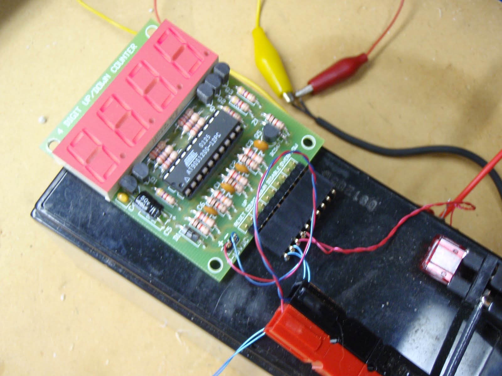
And the connector break-out allowed me to apply power to the motor for testing (right side, yellow leads) while monitoring the resistance of the 0-500 ohms position sensor (left side, red+black leads):

The system works nicely!

The next steps in reassembly are to re-grease the bearing races and ball bearings (using marine-grade grease), and the reassemble as shown in my previous post.
Overall, the motor repair was an interesting project, it was a lot of fun to take the totally non-functional unit apart and then reassemble it into something that works again!
For anyone interested in more rotator repair information, read on to see the assembly in the next post, or check out the following web links:
General Yaesu G-5500 rotator repair:
http://www.sunsunsun.net/kd4app/amsat/g5500.htm
Yaesu G-5500 elevation rotator repair:
http://ivok.home.xs4all.nl/pa1ivo/G-5500.html
http://www.ocrg.org/W7KKE/rotor/rotor.html


